Posts

Week 8-9

Image
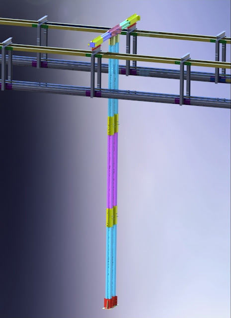
Figure 1. Final support During the last two to three weeks, I have been researching and designing supports in order to support the solar panels on top of the main structure.  I came up with two designs; most components of both designs are made out of sheet metal. However, based on my knowledge, manufacturing the first model (figure 2 and 3) might be hard because of the length of the pieces and the type of bends that they require. Due to the difficulty of manufacturing this support, I decided not to complete my design and did not put any bolt holes on the support.  Figure 2. Solar panel support 1 (isometric view) Figure 3. Solar panel support 1 (front view) For the solar panel supporting rail, I used a GS-MR-L Grasol rail (figure 3). This rail is made by extruding aluminum. Grasol also manufactures mounts in order to mount solar panels on the rails. They use a specific type of extruded aluminum support beam to support the rails. This allows the assemblers to adju

Week 5-7

Image
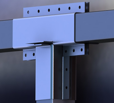
Figure 1. Full model For the past few weeks, I have been working on the main supporting structure. The support has to be strong enough to withstand the cyclic loads, and also the weight of the tracks, solar panels, bogies and the pod cars. Instead of using the commonly used beams, our team is working with cross beams, invented by a South African company called Milotek. Cross beams are made out of sheet metal, which are then filled with concrete. Welding and drilling into sheet metal can reduce the strength of the structure. In order to avoid reducing the strength of the cross beams, we are trying to avoid welding and drilling into the cross beams. One way to connect cross beams is to use friction clamps. Figure 2 shows the current design of the friction clamp. Due to a non-disclosure agreement, I cannot show the exploded view of my designs, so it might be hard to fully understand the different aspects of the design. In the current design of the cross beam, two plates which ar

Week 4

Image
This week, I worked on few more designs of clamps in order to connect cross beams to one another. The first clamp that I designed was another T-clamp. The T-clamp that I previously designed is not aesthetically pleasing, and it has flanges on multiple sides of it. This clamp can be seen in figure 1. The second design of the T-clamp can be seen in figure 2. The new design is also a friction clamp and by tightening nuts and bolts on the flanges, friction can be increased between the clamp and the cross beams; this stops the cross beams from moving. In the new design, I removed all the flanges except the one on top. The rest of the flanges were replaced by either flat plates or jogs.  Another plate would need to be welded on this flat plates. Then, the plates and the jogs would need to be tapped, so that the clamps can be assembled on one another using bolts. Figure 1. T-clamp # 1 Figure 2. T-clamp # 2 These clamps will be made out of sheet metal. A laser cutter, or a plasm

Week 3

Image
This week I worked on recreating the layout of the Swenson property on SolidWorks. I was given the layout in AutoCad (figure 1), but I was having problems importing it to SolidWorks. After trying multiple tricks to import the sketch, I finally decided to redraw everything from scratch. This was a time consuming tasks since the sketch was very detailed, and I had to get the coordinates of every point on AutoCad and use the same coordinates to draw the sketch on SolidWorks. Another hard part of this task was to duplicate the curves correctly. A minor change in the layout could have a major impact on the final layout of the test track. In order to save time, I decided to simplify the model and take out unnecessary points from the sketch. The final sketch can be seen in figure 2. Figure 1. Swenson property layout (AutoCad) Figure 2. Swenson property layout (SolidWorks) After recreating the layout of the Swenson property, I spend some time to become familiar with the structur

Week 2

Image
Week 2 I started this week by working on new designs to solve the problems that we are having with the switch. At the switch, the wheels of the bogie hit the front part of the rail, which causes vibration, is noisy, and puts a lot of stress on the bogie and the track. Besides the designs that I posted last week, I came up with a new design (figure 1) that uses cables to support the pod car at the switch. In this system the cable matches the speed of the bogie, and the bogie connects to the cable. After the connection has been made, the majority of the weight of the pod car and the bogie will be supported by the cable; this prevents the wheels of the bogie from colliding with the front part of the track even if the mechanism that allows the pod car to move on a single track would fail. Figure 1. Cables supporting the pod car. I also worked on a new mechanism for switching (figure 2). The current switching mechanism, switches the tracks by applied a force on the side of

Week 1

Image
Week 1 At Spartan Subway, I am in charge of finding a solution to support the tracks. The mechanism that is currently in place uses bogies that apply force to the side of the tracks with a set of wheels (figure 1). This allows the bogie to move on a single track. However, this causes one side of the bogie to be lower than the other side when it is not in contact with the track. Since, one side is lower than the other, when the wheels come in contact with the tracks again, they bang against them. This causes a lot of stress on the bogie and the track, makes noise, and causes discomfort for the passengers.  Also, since the wheels are touching the side of the tracks, it would be hard to use brackets or straight ribs on their side to support them. Figure 1. Current bogie mechanism. Figure 2 shows the position of the bogie right before switching. As it can be seen in this figure, one of the wheels is not in contact with the track. At this position, if the mechanism tha