Week 5-7

Figure 1. Full model
For the past few weeks, I have been working on the main supporting structure. The support has to be strong enough to withstand the cyclic loads, and also the weight of the tracks, solar panels, bogies and the pod cars. Instead of using the commonly used beams, our team is working with cross beams, invented by a South African company called Milotek. Cross beams are made out of sheet metal, which are then filled with concrete. Welding and drilling into sheet metal can reduce the strength of the structure. In order to avoid reducing the strength of the cross beams, we are trying to avoid welding and drilling into the cross beams. One way to connect cross beams is to use friction clamps. Figure 2 shows the current design of the friction clamp. Due to a non-disclosure agreement, I cannot show the exploded view of my designs, so it might be hard to fully understand the different aspects of the design. In the current design of the cross beam, two plates which are welded to the clamp make sure that both beams are evenly covered by the clamp. After tightening bolts and nuts on the sides of the clamp, the friction prevents the beams from moving. This method of connection have been tested and can be used in South Africa. Even though, the friction is high enough to create a strong connection, this method may not be approved in the U.S.. One solution to this problem is to use pneumatic pins in order to create a secondary connection between the clamps and the beams. However, the pins will reduce the strength of the beams, and removing them requires drilling. If a pin or a part had to be replaced, a hole will be left on the cross beams, and it is impossible to use a pin at the same location.

Figure 2. Friction Clamp
Due to the previously explained problem, I came up with a new design to secure the connection between the cross beams and the clamps. This design can be seen in figure 3. I added a piece to the end of each panel of the cross beams. This gives us 4 connection pieces at each end of the beams. These end pieces are part of the panels and are plasma cut and bent to give us the desired shape. After placing the beams on top of each other, the clamps are assembled on the beams. The end pieces of the beams go through the slots on the clamps. Then a plate goes in between the clamps and the beams; this increases the strength of the support. At the end, the clamps are tightened using nuts and bolts. The friction caused by the clamps and the connection between the end pieces of the beams and the clamps keep the beams in place and prevents them from moving.

Figure 3. Vertical beam Connector
As long as the end pieces of the cross beams have gone through the slot on the clamps and the clamps are tightened using nuts and bolts, there is no need for any other type of connection. The friction caused by the clamps is strong enough to hold the beams in place. The connection between the end pieces of the beams and the slots on the clamps works as a safety in case the friction clamps fail to hold the beams in place. However, I was asked by Claude, the inventor of cross beams to design connectors to secure the connection between the end pieces and the clamps, so I came up with the following designs (figure 4). The part on the left side of the figure has to be hammered down, and the connection can be secured using a pin that goes through a hole which has aligned with the end piece of the beam. On the middle top figure, the connection is secured by assembling the red and blue pieces and then tightening the nuts and bolts. On the middle bottom figure, the connection is secured by placing the red piece in the slot and tightening the screw until the screw is fully extended. On the right figure, the triangular pieces have saw shaped sides. They need to be hammered to secure the connection. However, because they have a saw shape design on one side, they cannot be removed once they are in place. Thus, the tooth that is in contact with the end piece of the beam has to be broken in order to remove it.


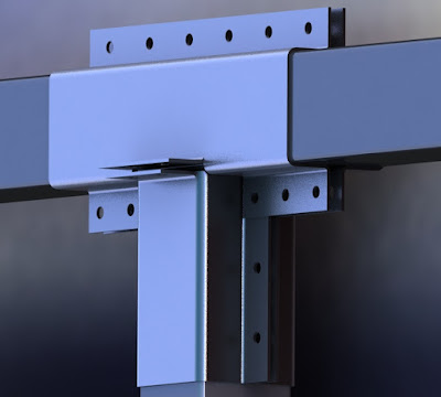
Figure 6. T-clamp

Figure 7. Track-beam connector

Figure 4. End piece connectors
In the past few weeks, I have also worked on new designs of the base support. My latest design of the base support can be seen in figure 5. The new design of the clamp is more secure and consists of a fewer parts compared to the previous designs. In the new design, the beams will be bolted down on the base plate. The green support will then be assembled and welded on the clamps. Then the clamps will be bolted on the bottom plate, and the friction will be increased on the clamps using nuts and bolts until the friction is strong enough to support the beams.

Figure 5. Base support
Just like the previous clamps, the T-clamps (figure 6) make the same type of connection with the cross beams. The end pieces of the cross beams either get connected to the clamps through the slots or get sandwiched between the flanges of the clamps. Then, the connection is secured by tightening nuts and bolts until the friction is large enough to prevent the beams from moving.

Figure 6. T-clamp
Lastly, I designed a clamp to connect the horizontal beams to the tracks; this design can be seen in figure 7. First the nuts and bolts on the top flanges have to be placed to hold the clamp in place. Then, the end pieces of the beams have to get connected to the flanges using nuts and bolts. After that, two L-brackets (shown in red) will secure the connection between the clamp and the I-beam, which is connected to the track. This connected is secured using nuts and bolts. At the end, the friction between the clamp and the beam has to be increased by tightening the nuts and bolts.

Figure 7. Track-beam connector


Comments
Post a Comment