Week 4
This week, I worked on few more designs of clamps in order to connect cross beams to one another. The first clamp that I designed was another T-clamp. The T-clamp that I previously designed is not aesthetically pleasing, and it has flanges on multiple sides of it. This clamp can be seen in figure 1. The second design of the T-clamp can be seen in figure 2. The new design is also a friction clamp and by tightening nuts and bolts on the flanges, friction can be increased between the clamp and the cross beams; this stops the cross beams from moving. In the new design, I removed all the flanges except the one on top. The rest of the flanges were replaced by either flat plates or jogs. Another plate would need to be welded on this flat plates. Then, the plates and the jogs would need to be tapped, so that the clamps can be assembled on one another using bolts.
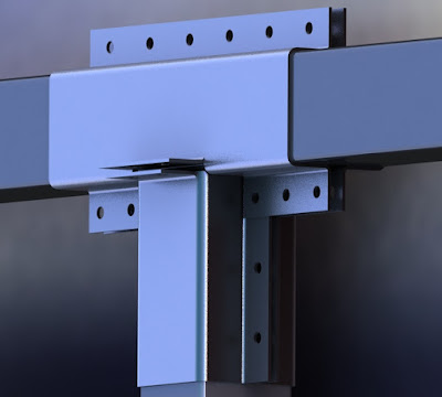

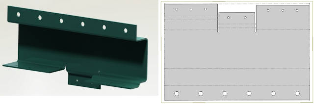


Figure 1. T-clamp # 1
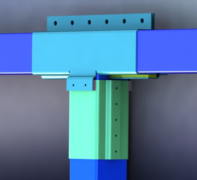
Figure 2. T-clamp # 2
These clamps will be made out of sheet metal. A laser cutter, or a plasma cutter can be used to cut the pattern on a sheet metal as seen in figure 3. Then, these sheets need to be bent from the marked spots in order to get the piece shown on the left side of figure 3.

Figure 3. Flattened clamp
After the T-clamps, I started working on the clamps which would connect the vertical beams to each other. This clamp can be seen in figure 3. Just like the previous designs, this clamp is a friction clamp. Figure 4 shows the exploded view of this piece. The green parts in this figure have to be welded on one another. This piece then goes in between the vertical clamps, which would prevent the beams from moving. The main pieces of the clamp will be bolted on each other from the sides. At the end, the friction between the clamp and the beams can be increased by tightening the bolts and nuts on the flanges.

Figure 4. Vertical beams Clamp

Figure 5. Exploded view of the vertical beam clamp
At the end, I designed a clamp for the base of the support. This friction clamp is shown in figure 5. The clamps will be placed on a sheet metal which is previously cut for the clamps to fit perfectly on it. After placing the clamps on top of this sheet of metal, another sheet of metal goes on top of the base of the flange. This stops the flange from moving around. Then both sheets will be bolted down to the ground. The side supports will then be assembled and welded on the flanges and the base plate; this increases the strength of the support. The yellow crossed plates can also be added to the support to increase its strength.

Figure 6. Base support

Figure 7. Exploded view of the base support.


Comments
Post a Comment