Week 1
Week 1

At Spartan Subway, I am in charge of finding a solution to support the tracks. The mechanism that is currently in place uses bogies that apply force to the side of the tracks with a set of wheels (figure 1). This allows the bogie to move on a single track. However, this causes one side of the bogie to be lower than the other side when it is not in contact with the track. Since, one side is lower than the other, when the wheels come in contact with the tracks again, they bang against them. This causes a lot of stress on the bogie and the track, makes noise, and causes discomfort for the passengers. Also, since the wheels are touching the side of the tracks, it would be hard to use brackets or straight ribs on their side to support them.

Figure 1. Current bogie mechanism.
Figure 2 shows the position of the bogie right before switching. As it can be seen in this figure, one of the wheels is not in contact with the track. At this position, if the mechanism that is holding the bogie in place fails, the bogie will fall from the side and will hit the front of the track. At a speed of 25-35 miles per hour, this impact can cause death or serious injuries.

Figure 2. Bogie at the switching position.
Our team, also needs to find a solution to support the tracks. A critical point which requires support is the part of the track which is at the switch. As it can be seen in figure 3, the closest support that can be placed in between the tracks is far from the switch; the red circle represents the location of the support.


Figure 3. Position of the pod cars near the switch.
In order to solve these problems, I came up with a new track/bogie system, and I designed a simplified model of the system using SolidWorks, My model consists of a second set of tracks, which are placed above the main tracks. Another set of bogies are also placed on top of the main ones. This design can be seen in figure 4 and 5. At the switch, the second set of bogies come in contact with the upper tracks, which results in lifting the bottom tracks; they can be lifted by giving a slope to the upper track before and after the switch (figure 6). A spring damper system can be used in order to make this transition as smooth as possible. The upper tracks and the wheels of the upper bogie are much wider than the bottom one. This prevents the wheels from falling into the groove. However, since the wide wheels create a lot of friction, and are not efficient, they should only come in contact with the tracks at the switch.

Figure 4. New bogies.
Figure 5. Simplified model of the proposed system.

Figure 6. Side view of the upper and lower tracks.
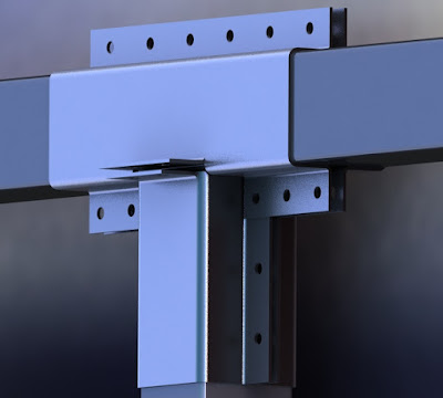
The tracks of the previous design and the new design can be supported by columns on either the sides of the tracks or in between them. As it can be seen in figure 7, the tracks can be supported with a beam connected to the main structure if it is desired to have the columns on the side of the tracks.

Figure 7. Support of the tracks using side columns.
If it is required to have the column in between the tracks, the tracks can be supported with cables connected to a column (Figure 8).

Figure 8. Support of the tracks using a mid column.
For the upcoming week, I am planning on coming up with a new solution to support the tracks, and to switch the direction of the bogies.

Comments
Post a Comment