Week 2
Week 2
I started this week by
working on new designs to solve the problems that we are having with the
switch. At the switch, the wheels of the bogie hit the front part of the rail,
which causes vibration, is noisy, and puts a lot of stress on the bogie and the
track. Besides the designs that I posted last week, I came up with a new design
(figure 1) that uses cables to support the pod car at the switch. In this system
the cable matches the speed of the bogie, and the bogie connects to the cable.
After the connection has been made, the majority of the weight of the pod car
and the bogie will be supported by the cable; this prevents the wheels of the
bogie from colliding with the front part of the track even if the mechanism
that allows the pod car to move on a single track would fail.

Figure 1. Cables supporting the pod car.
I also worked on a new
mechanism for switching (figure 2). The current switching mechanism, switches
the tracks by applied a force on the side of the track using a set of wheels.
This disables us from placing ribs or brackets flat on the side of the track.
The mechanism that I have proposed uses another set of rails underneath the
previous ones. These rails will be hollow inside, with a grove on one side.
Before switching, a mechanism pushes a set of wheels inside the rail on one
side of the track. After the wheels are fully extended, they rotate 90 degrees
and come in contact with the inner side of the rail. The wheels then prevent
the pod car from moving in the opposite direction.

Figure 2. Switch.
After the switch, I
started working on the main supports (figure 3). To simplify the model, I used
rectangular beams instead of cross beams. Since, the cross beams cannot be
bent, I used clamps to connect the beams to each other in order to create a
curve to support the load of the horizontal beam.

Figure 3. Main support.
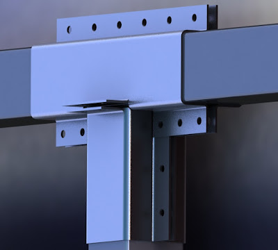
Initially, I was
planning on bolting down the center and the side clamps (figure 4) to the vertical
and horizontal beams. In order to avoid using bolts, which would reduce the
strength of the material, it is possible to use cables to connect the right
clamp and the bottom clamp in figure 4 to the clamp on the top left of the
figure. The tension created by the cable and the beams in between the clamps
would prevent the clamps from moving.

Figure 4. Clamps.
After designing the main
support, I assembled all the parts to show what the semi-complete system looks
like. The assembled parts can be seen in figure 5.

Figure 5. Semi-complete system.
As I mentioned in my
previous post, the new system that I am proposing uses another set of bogies,
which comes in contact with the upper tracks and lift the bottom bogies from
the track; this prevents the wheels of the bottom bogie from colliding with the
front part of the rail. The upper tracks start right before the switch and end
right after it. I made the upper tracks with a slope (figure 6), so that the
wheels of the top bogie would slowly come in contact with the upper tracks and
lift the bottom bogies of the rails. This transition can be made as smooth as
possible by adding springs and dampers to the system.

Figure 6. Curved upper tracks.
After finishing my
designs, I met Claude, the inventor of cross beams. Based on the information
that I received from him, we are not going to use the support that I have designed.
For the new design, the cross beams will be connected to each other using
friction joints, and the tracks will be five meters away from each other. Since
this distance is very small, the arched support that I added to my design can
be removed, and if a support is needed, a single cross beam can be used to
support the weight of the horizontal beam.
Currently I am mapping
the layout of the tracks that we are going to build in the near future. We have
a small area to work with and there are many obstacles on our way. The layout has
to meet certain criteria in order to get approved by the city hall.


Comments
Post a Comment